

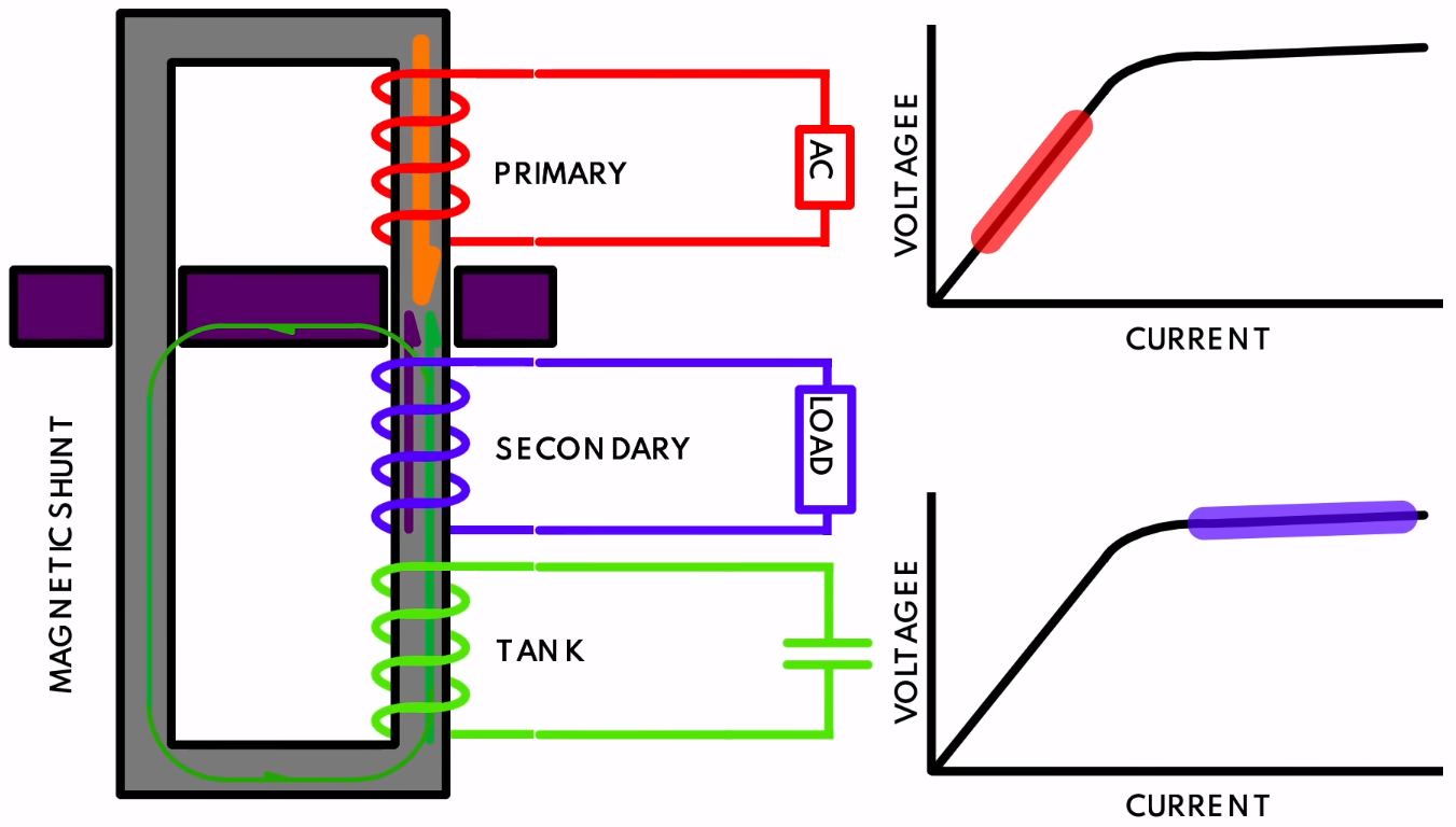
While troubleshooting the power supply of a 1970s Centurion system, [Usagi Electrics] came across a fascinating feature of these units: the ferroresonant, or constant voltage transformer (CVT). The main difference between a regular transformer and a CVT is that the former has a quite direct correlation between the input and output voltage, as the magnetic flux induced on the primary side is directly translated to the secondary (output) side.
A CVT adds a second element on the secondary side in the form of a tank circuit (LC circuit) – essentially a large capacitor – along with a magnetic shunt that ‘short circuits’ part of the magnetic flux between the primary and secondary side. The result of this is that even as the primary side is kept well below the saturation point where efficiency plummets, the secondary side is kept within this saturation region, enabling a very constant output voltage across a wide range of input voltages. For the Centurion’s power supply this input range goes from 90 to 130 VAC.
Although this is an obvious benefit of CVTs, the drawbacks are also plentiful. One is that keeping the secondary side in saturation produces more waste heat, another is that CVTs produce a distinct whine and the CVT is much more sensitive to grid frequency changes than a regular transformer. Even so, they still find ..
Support the originator by clicking the read the rest link below.


