

An Analogue to Digital Converter (ADC) is at its core a straight-forward device: by measuring an analog voltage within a set range and converting the measured level to a digital value we can use this measurement value in our code. Through the use of embedded ADCs in microcontrollers we can address many essential use cases, ranging from measuring the setting on a potentiometer, to reading an analog output line on sensors, including the MCU’s internal temperature and voltage sensors.
The ADCs found in STM32 MCUs have a resolution between 12 to 16 bits, with the former being the most common type. An ADC can be configured to reduce this resolution, set a specific sampling speed, and set up a multi-mode configuration depending on the exact ADC peripheral. STM32 MCUs feature at least a single ADC peripheral, while some have multiple. In this article we will take a look at how to configure and use the basic features of the ADCs in STM32 MCUs, specifically the ADCs found in F0 and the ADC5_V1_1 type as found in most F3-family MCUs.
Setting Things Up
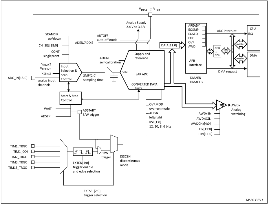
STM32F0 ADC block diagram (RM0091, 13.4).
There are three essential items to take care of when configuring an ADC device:
Enabling its clock in its Reset and Clock Control (RCC) enable register.
Calibrating the ADC device.
Picking an ADC common clock source.
The first item should be obvious, as it is the standard procedure as with any other peripheral device on STM32. Even so there is a bit of a gotcha here on some STM32 MCUs. Specifically on MCUs like the F334, its two ADC devices (ADC1 and ADC2) use the same cl ..
Support the originator by clicking the read the rest link below.


